Equip-Link
Choosing the right LC connector transceiver can feel simple until a network link fails during installation. The connector may fit, yet the optical specifications may not. This guide examines the practical decisions behind reliable fiber connectivity, from interface type to transmission distance.
An experienced installer checks more than the LC connection. Data rate, fiber mode, wavelength, reach, and duplex operation must match the switch and cable. A 10Gbps module for multimode fiber may be unsuitable for a single-mode link. Vendor coding also matters, especially in equipment with strict compatibility controls. Read the product datasheet carefully. Confirm operating temperature, power consumption, diagnostic monitoring, and supported standards before ordering.
Small details matter.
Real projects often reveal overlooked problems. A clean-looking connector can still have dust inside its ferrule. A short cable may exceed the transceiver’s minimum transmission distance. Some modules perform well in laboratory conditions but behave differently in crowded racks with limited airflow. Testing the link with approved cleaning tools, an optical power meter, and compatible equipment improves confidence. However, no checklist removes every risk. Specifications can be incomplete, and installation habits can vary between teams. A careful choice combines manufacturer evidence, field experience, and the actual network environment. This article helps readers compare LC connector transceiver options with a more disciplined approach, while recognizing that the cheapest or fastest module is not always the most dependable one.
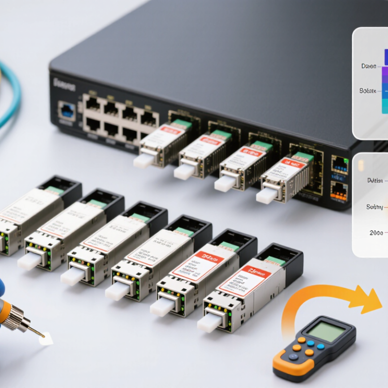
An LC connector transceiver is an optical interface used to send and receive data through fiber cable. It converts electrical signals into optical pulses and changes incoming light back into electrical signals. The LC connector provides a small, secure connection between the transceiver and the fiber patch cord. Its push-pull latch helps prevent accidental disconnection inside a crowded rack. Small part. Important job.
Its basic structure usually includes an optical engine, circuit board, housing, and duplex LC receptacle. The optical engine contains the transmitter and receiver elements. The circuit board manages signal conversion, monitoring, and communication with network equipment. The duplex receptacle holds two fiber channels, normally for transmit and receive paths. Inside the connector, ceramic ferrules help maintain accurate fiber alignment. A slight alignment error can increase insertion loss.
When defining its role, check the required data rate, transmission distance, wavelength, and fiber type. The transceiver must also match the equipment’s port and operating temperature. A module designed for multimode fiber may perform poorly with single-mode cable. I have seen installation problems caused by correct-looking connectors and incorrect polarity. That detail is easy to miss. Inspect the latch, dust caps, and fiber end face before installation. Compare measured loss with the technical data sheet, rather than trusting appearance alone. Even experienced technicians sometimes overlook clearance around the latch. That mistake deserves a second check.
How to Choose the Right LC Connector Transceiver?
Match Fiber Type, Wavelength, Speed, and Transmission Distance
Choosing an LC connector transceiver starts with the fiber already installed. Multimode fiber commonly supports shorter links and uses wavelengths near 850 nm. Single-mode fiber suits longer distances and often operates around 1310 nm or 1550 nm. Never assume the connector determines compatibility. The fiber type matters more.
Check the required data speed next. A transceiver designed for 1 Gb/s may not support a 10 Gb/s network. The switch, cable, and optical module must share the same standard. I once focused on connector size and overlooked the host port specification. That mistake caused unnecessary testing. It was a useful reminder.
Distance ratings need careful attention. A module rated for 2 kilometers may be unsuitable for a 10-kilometer link. Measure the actual cable route, including patch panels and service loops. Then compare the optical budget with connector and splice losses. Leave a reasonable margin. Dusty LC end faces can reduce that margin quickly. Clean them before testing.
Wavelength pairing also deserves attention. Transmit and receive paths must use compatible optical characteristics. Duplex links require correct polarity between both ends. Simplex designs need closer inspection. Temperature and diagnostic features can affect reliability in server rooms or outdoor cabinets. Specifications look clear, but field conditions are less forgiving. Check every value against the installation record before ordering.
Match the transceiver to the fiber type, wavelength, data rate, and required transmission distance. The chart shows representative maximum reach values for common LC duplex optical link profiles. Actual reach depends on fiber quality, optical budget, connector loss, and deployment conditions.
Selection guide: Multimode fiber is typically used for shorter, cost-sensitive links, while single-mode fiber supports longer distances. Higher data rates generally require optimized fiber, lower link loss, or a shorter transmission distance.
Choosing the right LC connector transceiver begins with the network device, not the connector alone. Check the switch, router, or server manual for supported speed, port type, and transceiver form factor. An LC interface may look identical across devices, yet electrical signaling and firmware support can differ. Compatibility matters.
Match the transceiver with the optical standard and cable already installed. A single-mode module usually supports longer distances and commonly uses narrower optical paths. Multimode modules suit shorter links inside buildings or data rooms. Confirm the wavelength, transmission distance, duplex or BiDi design, and fiber type. Also check the required data rate, such as 1G, 10G, or higher. In practice, I measure the link budget before ordering. A few extra connectors, dirty end faces, or a long patch cable can reduce signal quality. I have trusted a specification sheet too quickly before; field conditions proved less forgiving.
Tips: Clean both LC ends, then inspect them with suitable equipment. Compare the transceiver’s wavelength with the receiver’s requirements. Verify device compatibility through official documentation, not appearance. Check operating temperature for crowded racks. If monitoring functions are required, confirm digital diagnostics support. A small mismatch may still produce a link light, but unstable performance can appear later. Loose assumptions are costly.
| Transceiver Category | Typical Network Speed | Optical Wavelength | Fiber Type | Typical Transmission Distance | LC Connector Configuration | Common Optical Standard | Device Compatibility Check | Important Selection Notes |
|---|---|---|---|---|---|---|---|---|
| Short-Reach Gigabit Ethernet | 1.25 Gb/s | 850 nm | Multimode fiber, OM2/OM3/OM4 | Up to approximately 550 m, depending on fiber grade and link design | Duplex LC | 1000BASE-SX | Select a device port that supports 1000BASE-SX or a compatible 1 Gb/s optical module. | Use multimode fiber and verify the installed fiber type before choosing the module. |
| Long-Reach Gigabit Ethernet | 1.25 Gb/s | 1310 nm | Single-mode fiber, typically OS2 | Up to approximately 10 km | Duplex LC | 1000BASE-LX | Confirm that the switch, router, or media converter supports 1000BASE-LX at 1 Gb/s. | For multimode cabling, a mode-conditioning arrangement may be required in some installations. |
| 10 Gigabit Short-Reach | 10.3125 Gb/s | 850 nm | Multimode fiber, OM3/OM4 | Up to approximately 300 m on OM3 or 400 m on OM4 | Duplex LC | 10GBASE-SR | Verify that the device port supports 10 Gb/s Ethernet and the 10GBASE-SR optical interface. | Do not use single-mode fiber as a substitute without confirming the transceiver’s optical specification. |
| 10 Gigabit Long-Reach | 10.3125 Gb/s | 1310 nm | Single-mode fiber, OS2 | Up to approximately 10 km | Duplex LC | 10GBASE-LR | Check the host port type, supported data rate, and 10GBASE-LR interoperability requirements. | Confirm optical power budget and connector cleanliness for longer links. |
| 25 Gigabit Short-Reach | 25.78125 Gb/s | 850 nm | Multimode fiber, OM3/OM4 | Up to approximately 70 m on OM3 or 100 m on OM4 | Duplex LC | 25GBASE-SR | The network device must support a 25 Gb/s SFP28-class port and the selected optical specification. | Check whether the device supports the required forward error correction and link configuration. |
| 25 Gigabit Long-Reach | 25.78125 Gb/s | 1310 nm | Single-mode fiber, OS2 | Up to approximately 10 km | Duplex LC | 25GBASE-LR | Confirm SFP28 port support, 25 Gb/s operation, and the applicable host coding or FEC settings. | Use matched optical specifications at both ends and verify the available link budget. |
| 40 Gigabit Long-Reach | 41.25 Gb/s | Four wavelengths near 1310 nm | Single-mode fiber, OS2 | Up to approximately 10 km | Duplex LC | 40GBASE-LR4 | The device must provide a QSFP+ port with support for 40GBASE-LR4 or an explicitly compatible mode. | Because multiple optical lanes are multiplexed, use the specified duplex LC fiber path and avoid mixing unrelated 40 Gb/s standards. |
| 100 Gigabit Short-to-Medium Reach | 103.125 Gb/s | Four wavelengths in the 1310 nm band | Single-mode fiber, OS2 | Up to approximately 2 km | Duplex LC | 100GBASE-CWDM4 | Confirm that the QSFP28-class device port supports 100GBASE-CWDM4 and the required host-side FEC. | Use a matched CWDM4 module at the opposite end; this is not interchangeable with a 100G multimode parallel-optics module. |
| 100 Gigabit Long-Reach | 103.125 Gb/s | Four wavelengths near 1310 nm | Single-mode fiber, OS2 | Up to approximately 10 km | Duplex LC | 100GBASE-LR4 | Verify QSFP28 port support, optical standard, FEC requirements, and software recognition by the device. | Check the transceiver’s wavelength range and optical power budget before deployment. |
| Bidirectional Single-Fiber Link | Commonly 1, 10, or 25 Gb/s, depending on the module | Two different wavelengths, one for each direction | Single-mode fiber, OS2 | Depends on the selected optical specification; commonly 10 km or more | Simplex LC | Vendor-neutral BiDi optical specification; not a duplex Ethernet standard by itself | Both ends must use complementary wavelength pairs and matching speed and distance specifications. | Never connect two identical BiDi wavelengths together; verify transmit and receive wavelength pairing. |
Choosing the right LC connector transceiver starts with power, not connector shape. In field audits, I have seen compatible optics fail because switches could not supply enough power. Check the transceiver’s power class and the host equipment’s limits. Leave thermal headroom. Power consumption matters in dense panels. Higher draw increases heat around neighboring modules and reduces operating stability. Compare operating wavelength, transmission distance, and fiber type before approving the unit.
Temperature ratings should match the real enclosure, not just the room. A cool server room can hide hot spots near fans, cable bundles, or sealed cabinets. Measure the rack during peak traffic. Do not guess. Outdoor cabinets may require wider temperature tolerance and stronger protection against condensation. Duplexing also needs careful review. LC duplex modules use two fibers for simultaneous transmission and reception. If the network uses one fiber, a duplex transceiver may create unnecessary complexity. Confirm fiber count, polarity, and link direction.
Installation requirements often decide whether a good specification works in practice. Verify cage clearance, latch direction, bend radius, and access for cleaning. Technicians need enough space to remove the module without disturbing adjacent cables. Clean LC ends before insertion. I once treated connector cleaning as routine, then found intermittent loss after repeated patching. That mistake changed my inspection checklist. A bench test can pass while a crowded cabinet still creates strain. Recheck polarity after installation, especially when labels are unclear. Small errors survive.
Verify Quality, Reliability, and Total Cost Before Purchase
Cisco’s Annual Internet Report projected 29.3 billion networked devices by 2023, rising from 18.4 billion in 2018. That growth makes dependable optical links more important. An LC transceiver should pass strict insertion-loss and return-loss tests before shipment. Ask for test records, temperature results, and compatibility evidence. The LC interface should also align with IEC 61754-20 requirements. Small alignment errors can create unstable links, especially in dense racks.
Check reliability beyond the datasheet. Telcordia GR-326 testing covers connector durability, vibration, humidity, and repeated mating. Request failure-rate data and a clear warranty. Inspect the ceramic ferrule under magnification, not only the packaging. Clean connectors before installation. It sounds basic. Many avoidable faults begin there.
Purchase price is only one part of total cost. Compare power consumption, expected service life, replacement time, spare inventory, and remote troubleshooting support. A cheaper module may require more replacements or cause costly downtime. Uptime Institute’s outage research repeatedly shows that operational failures can create major financial losses, even when hardware costs seem modest. I would also test a sample batch in the actual switch and fiber path. Laboratory results alone are not enough. My earlier mistake was trusting identical specifications too quickly; real compatibility still needs proof.
Check the installed fiber type before choosing the transceiver. Multimode fiber usually suits shorter links near 850 nm. Single-mode fiber commonly supports longer links near 1310 nm or 1550 nm. The connector shape alone proves little. Fiber type matters more.
Match the transceiver speed with the switch, cable, and optical standard. A 1 Gb/s module may not support a 10 Gb/s network. Check the device manual carefully. I once checked the connector first and missed the host port specification. That caused avoidable testing.
Measure the complete cable route, including patch panels, connectors, and service loops. A 2-kilometer module may fail on a 10-kilometer link. Compare the distance rating with the optical budget. Leave extra margin. Dusty end faces can consume it quickly.
Transmit and receive paths need compatible optical characteristics. Confirm the wavelength at both ends. Duplex links also require correct polarity. Simplex links need closer inspection. Small details matter.
Read the official device documentation for speed, port type, form factor, and supported modules. Two LC interfaces may look identical but use different electrical signaling. Firmware support can also matter. Appearance is not proof.
Clean both LC end faces and inspect them with suitable equipment. Examine the ceramic ferrule under magnification when possible. Check for dust, scratches, or poor alignment. Clean them first. Packaging inspection is not enough.
Ask for insertion-loss, return-loss, temperature, and compatibility test records. Request durability data, failure-rate information, and warranty terms. Connector testing should address vibration, humidity, and repeated mating. A datasheet alone may not reveal field problems.
Consider power use, service life, replacement time, spare inventory, and troubleshooting support. A cheaper module may cause more replacements or longer downtime. Test a sample batch in the actual switch and fiber path. I have trusted matching specifications too quickly. Real installations can be less forgiving.
Choosing the right LC connector transceiver starts with understanding its role and basic structure in a fiber optic network. This compact component converts electrical signals into optical signals and connects equipment through an LC interface. Before purchasing, confirm the fiber type, operating wavelength, data rate, and required transmission distance to ensure the transceiver can support your network design. It is equally important to check compatibility with switches, routers, and other devices, as well as compliance with relevant optical and communication standards.
Other practical factors also affect the final choice. Compare power consumption, operating temperature, duplex or simplex transmission, and installation requirements according to the working environment. A reliable LC connector transceiver should provide stable performance, accurate specifications, and suitable protection against normal operating conditions. Finally, evaluate product quality, testing information, warranty coverage, and long-term maintenance costs rather than focusing only on the initial price. A balanced assessment will help ensure dependable connectivity and better overall value.
