Equip-Link
Equip-Link
Equip-Link
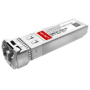
Explore our premium SMT connectors, optical transceivers, and copper interface solutions engineered for extreme environmental tolerance and high-speed data transmission.
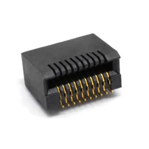
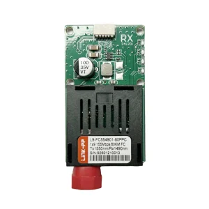
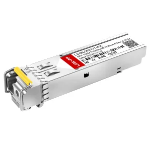
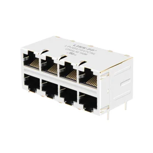
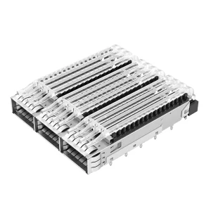
In the architecture of high-speed optical communications, Small Form-factor Pluggable (SFP) cages and connectors serve as the mechanical, thermal, and electrical interface between transceivers and circuit board systems. As global network capacity surges—fueled by hyper-scale data centers, distributed edge nodes, and high-frequency artificial intelligence workloads—traditional interconnect infrastructures face massive constraints in signal integrity and electromagnetic compatibility.
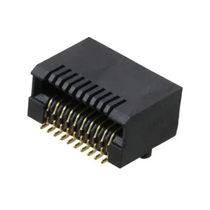
An SFP connector is a precision 20-position card-edge receptacle engineered to maintain precise impedance matching (typically 100 ohms differential) while operating at speeds upward of 28Gbps per lane in SFP28 configurations, extending even to 112Gbps per channel in advanced QSFP-DD designs. The surrounding copper-alloy metal SFP cage is equally critical; it provides necessary grounding, prevents electromagnetic interference (EMI) leakage via built-in spring fingers, and acts as a primary heat path for thermal dissipation.
For global procurement managers, identifying a high-tier manufacturer and exporter of SFP cages and SFP connectors requires careful verification of raw material grading, plating thickness (e.g., 30u" Gold Pleating vs 15u" variations), dimensional tolerances, and compliance with Multi-Source Agreements (MSA).
How hyper-scale networking, AI workloads, and edge computing are shaping the design rules for SFP cages and connector systems.
With standard gigabit Ethernet giving way to 25G and 50G per lane architectures, modern optical cages must feature enhanced impedance control. Pin layout and internal dielectric components of SFP connectors are engineered to mitigate cross-talk and insertion loss at frequencies exceeding 28 GHz.
As switch faceplates become densely packed, dual-row (stacked 2xN) SFP cages are replacing single-row configurations. These compact architectures restrict airflow, making integrated light pipes, heat sinks, and structural ventilation vents critical components of high-performance assemblies.
Under IEEE 802.3 and FCC Part 15 regulations, high-speed lines must minimize electromagnetic emission. Premium SFP cages utilize conductive elastomeric gaskets or mechanical metal fingers that ground the transceiver module to the chassis panel, neutralizing RF emissions.
Years Industry Expertise
Annual Export Revenue
Supply Chain Partners
New Products Launched Annually
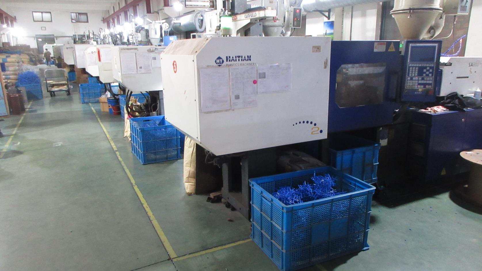
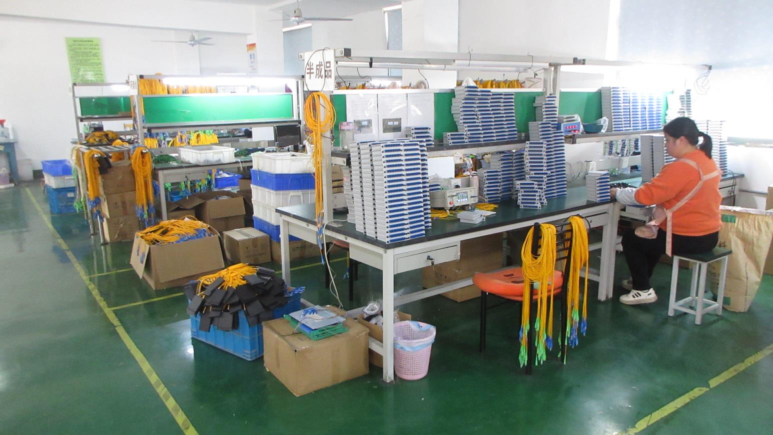
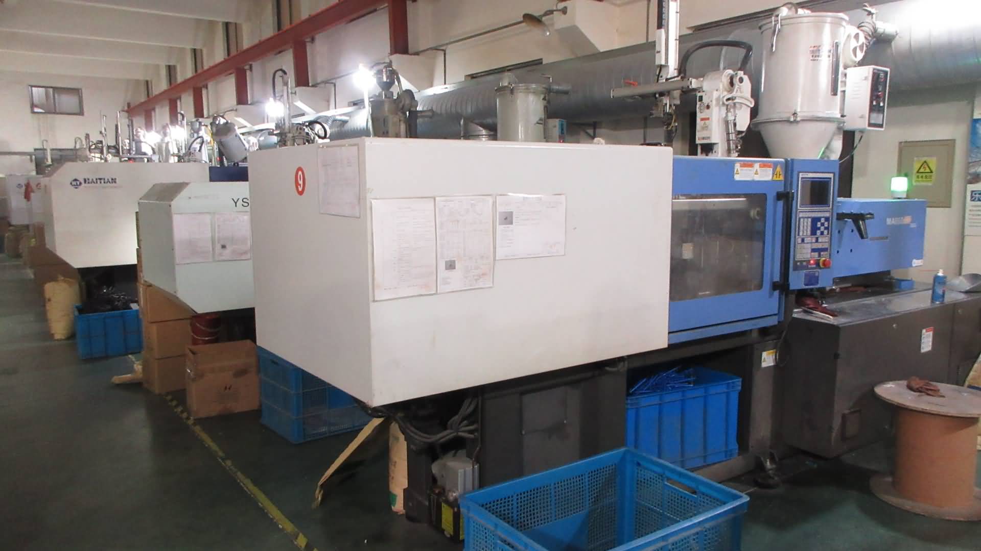
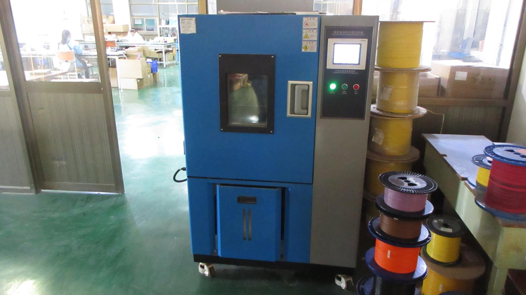
Step inside Equip-Link’s advanced manufacturing facility. Discover how automated assembly, precise injection molding, and intense verification chambers build reliability into every port.
Located in Shenzhen's tech corridor, Equip-Link’s production facility integrates high-precision injection molding, automated contact terminal insertion, and strict quality control workflows. Backed by 9 years of export experience, our manufacturing line caters to critical telecom system integrators, optical transceiver vendors, and OEM network hardware distributors across North America, Europe, and Asia.
Our Quality Assurance program utilizes 36 professional inspectors who monitor raw materials and execute real-time production checks. Key to our production resilience is the relationship with over 1,280 qualified partners. This broad integration safeguards raw material access—such as high-grade engineering polymers (LCP) and high-performance copper alloys—ensuring steady lead times even during global supply line fluctuations.
Every single batch of SFP connectors and cages undergoes mechanical insertion testing, gold plating verification, and strict dimensional audits to ensure standard compatibility with MSA partners like TE, Amphenol, and Molex.
| Established | 2017 (14 years industry engineering background) |
| Factory Area | Modern specialized facility |
| R&D Department | 68 professional R&D engineers |
| Major Markets | North America, Europe, SE Asia, Middle East, S. America |
| Customization Capacity | Firmware matching, custom plating, OEM/ODM solutions |

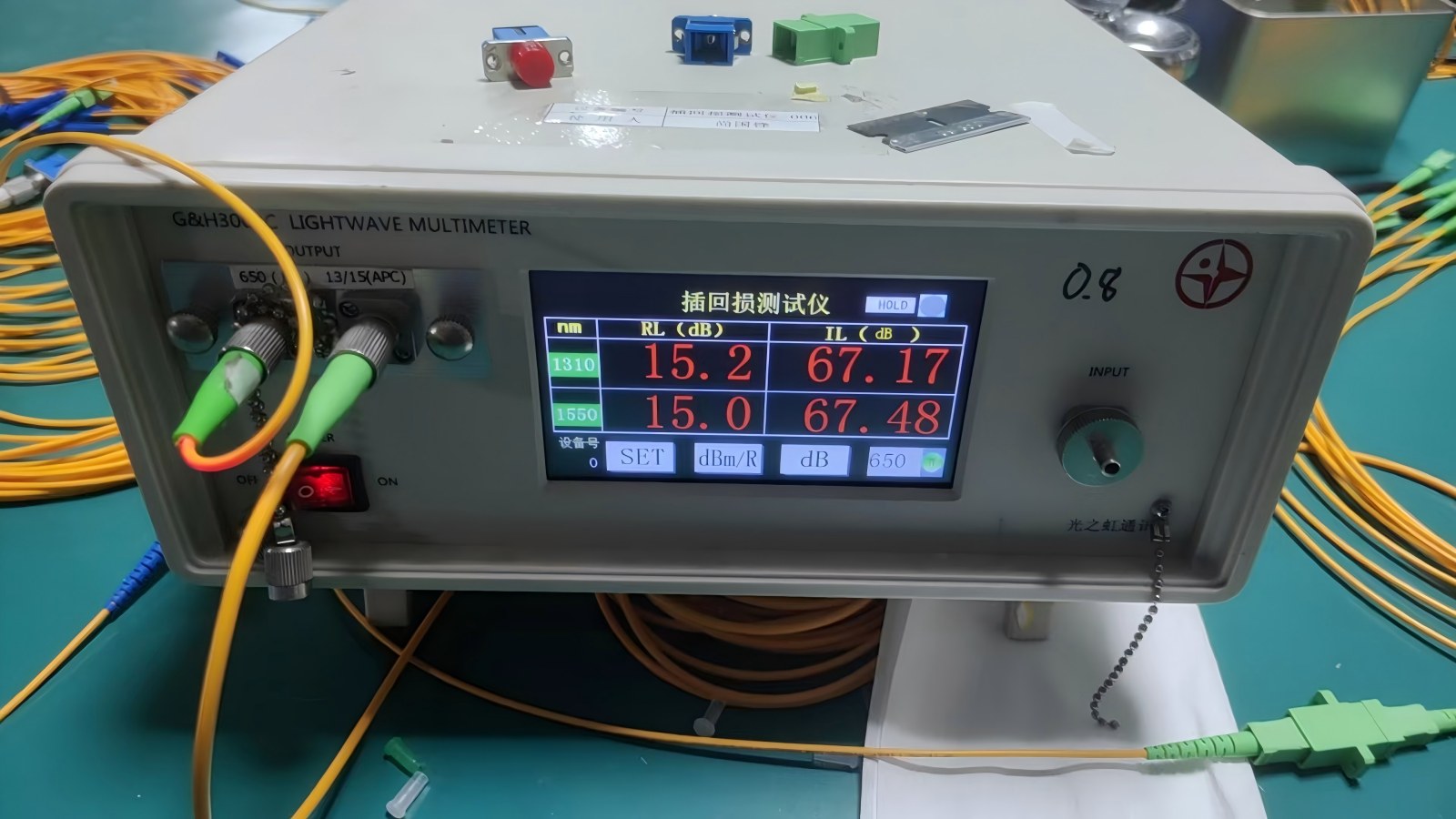
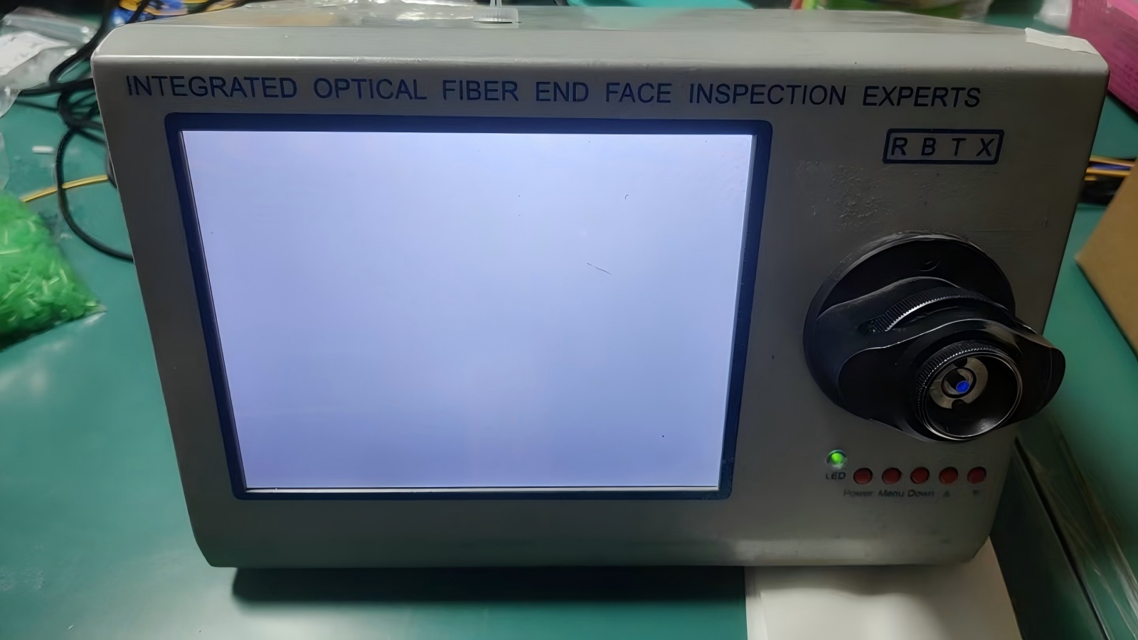
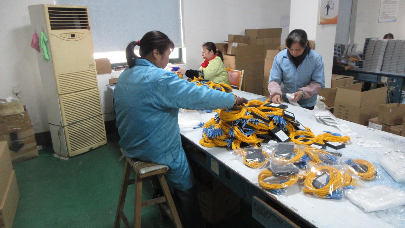
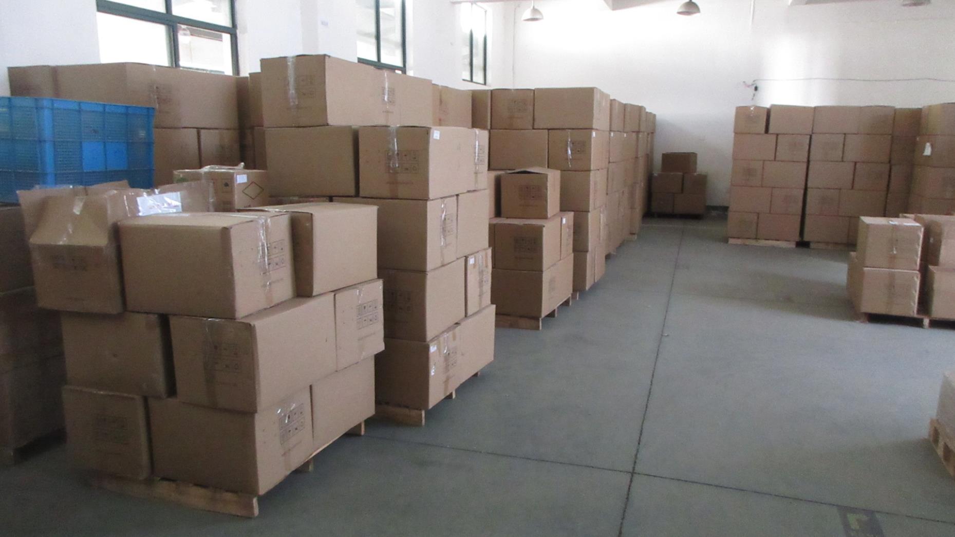
Avoid deployment delays and interface incompatibilities by implementing a strict quality-metric scorecard for interconnect components.
High-reliability environments require hardware verified by Telcordia GR-1217-CORE standards. Thermal cycling, humidity exposure, and corrosive atmosphere testing ensure SFP connectors retain electrical contact resistance beneath a threshold limit of Δ10mΩ.
Cages must guarantee a precise physical envelope to fit standard transceivers. Variations in sheet metal thickness can cause loose coupling (EMI leakage) or excessive friction, which risks damaging internal PCB trace pads during insertion.
With 68 professional engineers, Equip-Link offers customizable solutions including varied light-pipe offsets, heat-sink heights, custom solder pastes, and specialty gold plating configurations (from 15u" to 30u") to meet exact design specifications.
Clear guidance addressing technical issues, materials selection, and installation specifications raised by telecom hardware engineers.
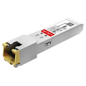
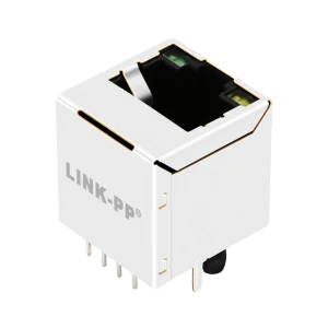
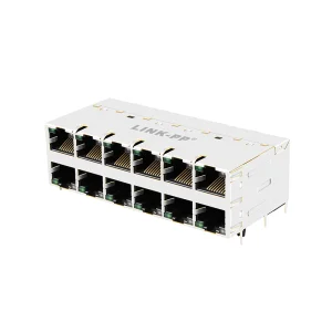
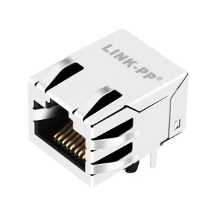
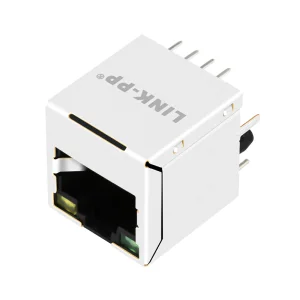
Explore the remainder of our portfolio including rugged RJ45 modular jacks, fiber-channel optical transceivers, and light-pipe-enabled SFP cages.