Equip-Link
Equip-Link
Equip-Link
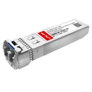
Deploy industry-grade transceivers, network interfaces, and structured loopback platforms engineered for modern telecom infrastructure.
In the rapidly scaling domains of optical telecommunications and hyperscale data centers, Ethernet Loopback Connectors (also referred to as loopback plugs or loopback adapters) serve as a fundamental tool for network validation, diagnostics, and loop testing. By routing outgoing signals back to the receiver, loopbacks enable engineers to isolate physical layer issues and verify optical module operability.
As networks migrate from legacy 10G/25G architectures to 100G, 400G, and next-generation 800G platforms, the requirements for signal attenuation, insertion loss, and thermal dissipation in optical loopback modules have increased exponentially. Precision engineering prevents diagnostic devices from introducing errors during loop tests.
The explosive rise of AI workloads demands ultra-low latency. High-density fiber diagnostic equipment must perform tests instantly. Advanced QSFP-DD and OSFP loopback modules now integrate thermal simulation and customizable power dissipation profiles to mimic real-world network loads.
Environmental standards such as RoHS and REACH demand lead-free, low-smoke zero-halogen (LSZH) materials. Industrial-grade injection molding processes ensure the loopbacks sustain thousands of cycles without physical degradation, maintaining strict optical alignment.
Global buyers, system integrators, and telecom operators evaluate Ethernet loopback connectors based on performance stability, structural tolerances, and custom coding capabilities. Here are the core metrics procurement directors focus on during auditing:
| Evaluation Parameter | Technical Benchmark Standard | Critical Sourcing Impact |
|---|---|---|
| Insertion Loss (IL) | ≤ 0.2dB (Super-low loss grade) | Prevents false positive diagnostics in marginal optical budgets. |
| Return Loss (RL) | ≥ 50dB (UPC), ≥ 60dB (APC) | Eliminates signal reflections back into laser diodes, preserving transmitter health. |
| EEPROM Custom Programming | Configurable power emulation (1W to 5W) | Allows diagnostic tools to mimic actual transceiver power consumption and thermal load. |
| Mating Durability | > 1000 mating cycles | Saves cost and ensures tool longevity inside testing environments and labs. |
Our connectors and loopback components operate at the intersection of core infrastructures, ensuring reliable packet loopback diagnostics from physical connectors up to active optical modules.
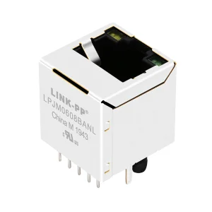
Deploying copper RJ45 loopback adapters and fiber loopbacks to verify patch panels, switch port connectivity, and localized transmission parameters. Essential for pre-commissioning infrastructure verification.
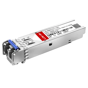
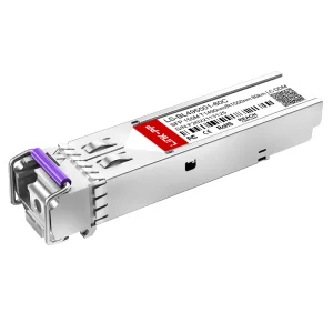
Using passive SFP+ / QSFP28 / QSFP-DD loopbacks to perform burn-in testing of switches and network cards, ensuring thermal parameters and communication links remain robust under maximum stress.
Waterproof RJ45 loopbacks and shielded transceivers designed for heavy EMI/RFI environments, protecting critical diagnostic links from factory-floor noise and physical contaminants.
Founded in 2017, Equip-Link Intelligent Equipment (Shenzhen) Co., Ltd. is a premier manufacturer and supplier of optical transceivers, structured copper connectors, and comprehensive fiber optic communication diagnostic solutions. We design, manufacture, and distribute components engineered to support AI infrastructures, telecom carriers, and enterprise networks.
We boast 9 years of export experience and a network of over 1,280 qualified supply chain partners. Our testing workflow operates under rigorous quality frameworks, featuring 36 dedicated quality assurance inspectors overseeing every step from inbound raw materials to final functional checks.
Equip-Link utilizes high-end injection molding equipment, precision fiber alignment systems, and advanced testing setups to guarantee the structural integrity and performance parameters of our diagnostic components.

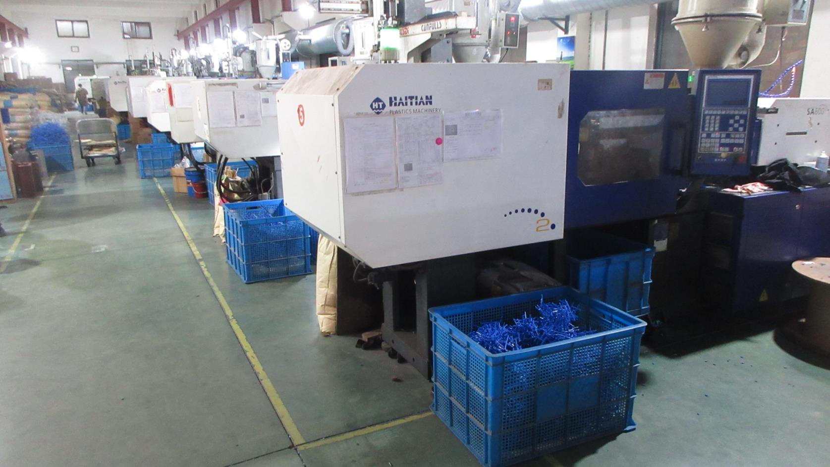
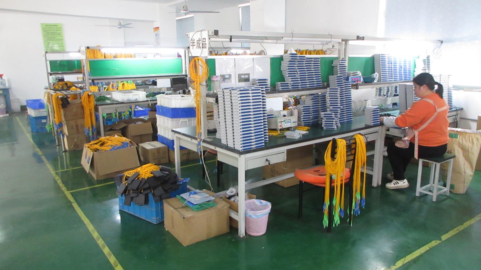
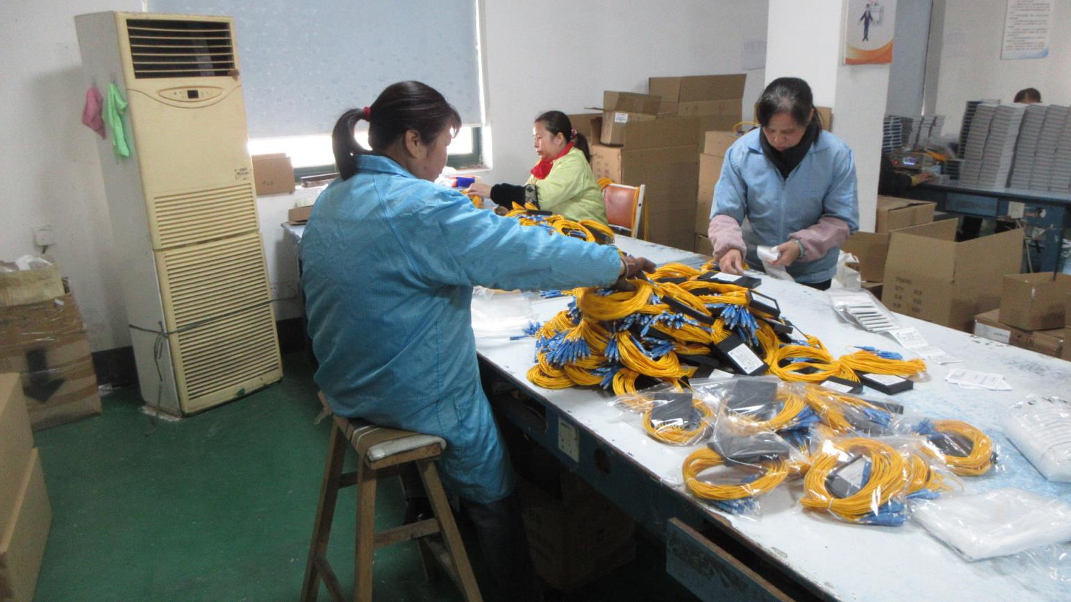

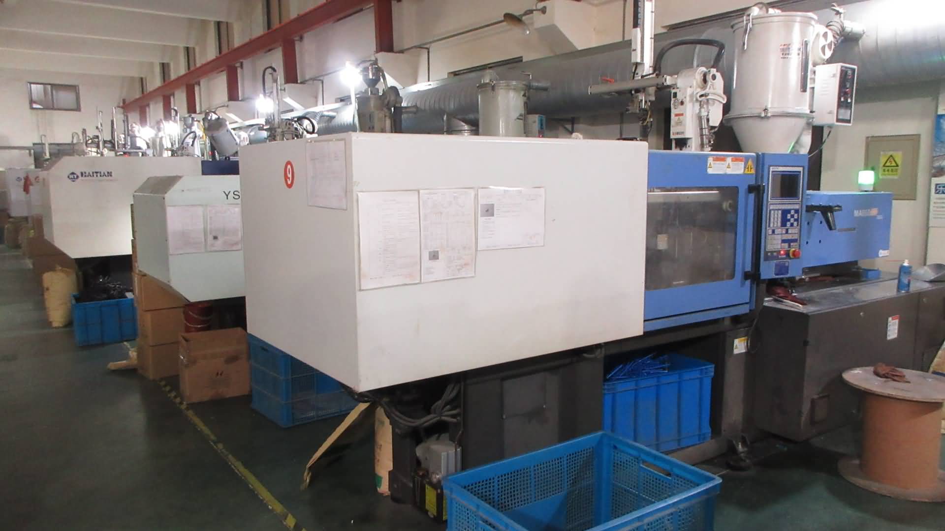
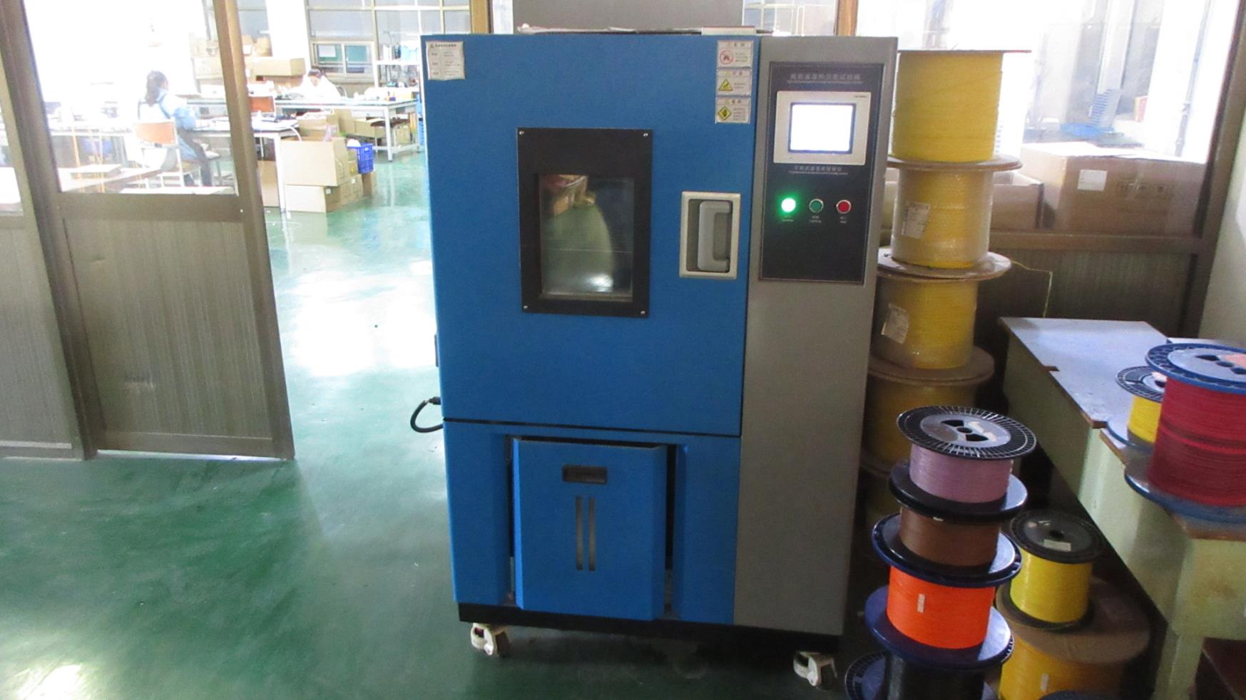
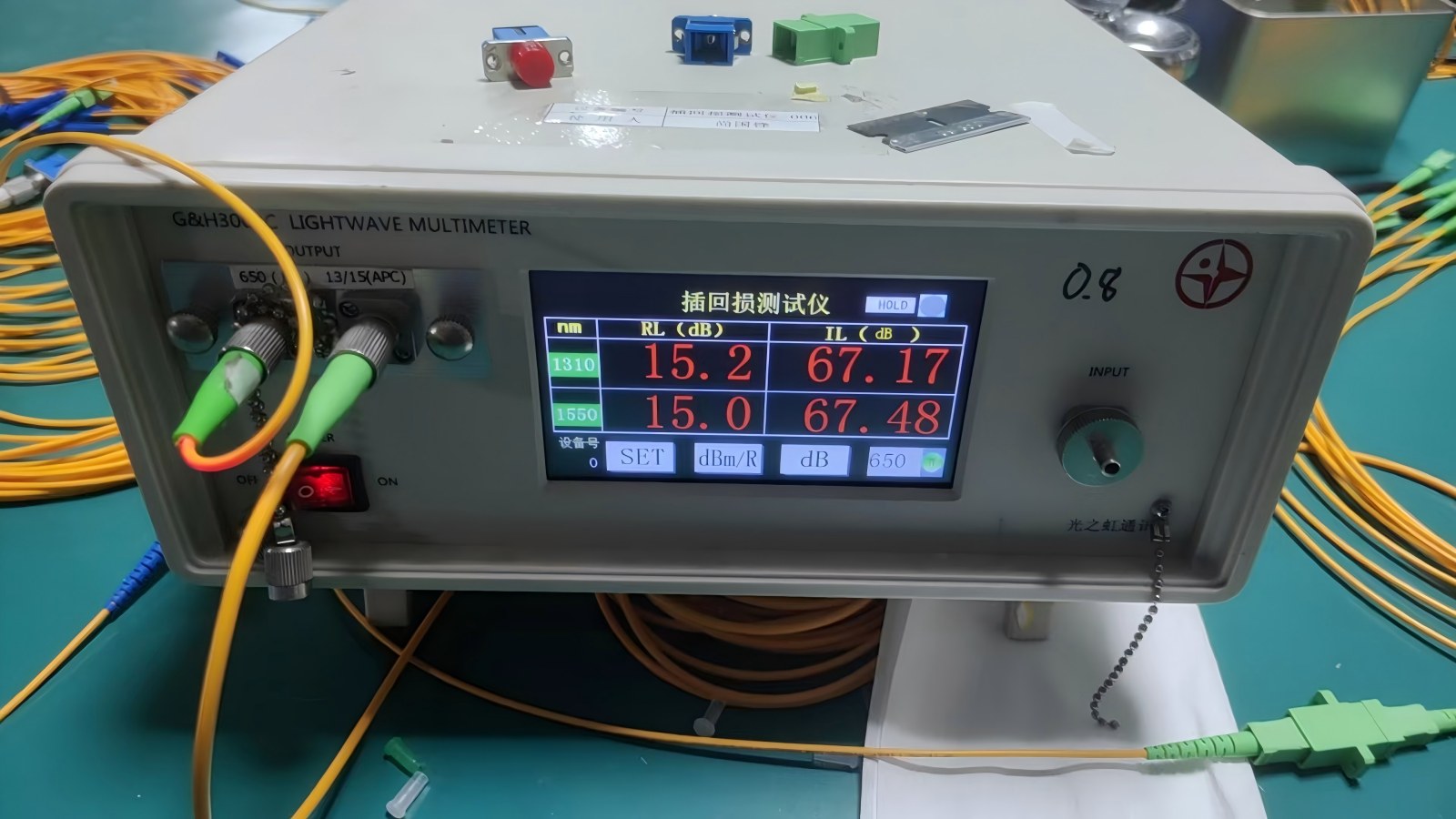
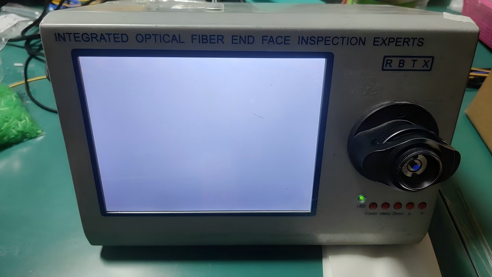
Diagnostic technology continues to advance alongside data rate scaling. The Equip-Link design laboratory is charting a clear roadmap to meet the high demands of the next decade of infrastructure development:
Integration of MCU modules into SFP28/QSFP28/QSFP-DD form factors, enabling engineers to adjust attenuation, monitor return temperature, and track diagnostic data via software controls during network validation.
Developing micro-loopback geometries aligned with co-packaged optics (CPO) standards, ensuring minimal signal degradation when testing ultra-high-density silicon photonics hardware.
Providing custom multi-channel loopbacks configured to emulate continuous high-speed data flow for burn-in, testing up to 800 Gbps and beyond in modern AI clusters.
Securing reliable hardware requires robust supply channels and localized integration capabilities. Equip-Link provides a multi-layer framework to guarantee quality and regulatory compliance:
All transceivers, network ports, and custom loopback interfaces conform strictly to international standards, including FCC, CE, RoHS, and REACH. Inbound testing and environmental simulation ensure that every batch of material meets flame-retardant and anti-static standards.
We supply private labeling, custom firmware programming (matching Cisco, Juniper, Arista, and HP EEPROM tables), and bespoke packaging layouts. This ensures that the diagnostic devices function seamlessly inside target switch ecosystems.
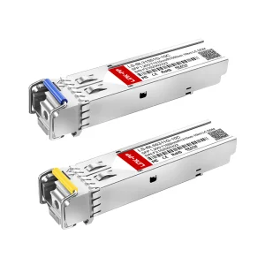
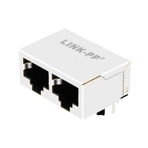
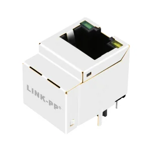
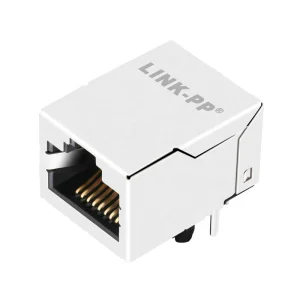
Explore high-durability connectivity components and SFP-compatible transceivers designed for low return loss and maximum uptime.